
A Mounting Jig for use with 35mm Stereo
Cardboard Mounts
NOTE: An initial production run of
66 units was produced in late 1996. Depending on demand, there may be another
production run. If you interested in this jig please contact us. For orders
and enquiries in Australia or elswhere, send email to: kiewavly@werple.net.au
Basic Design Aim:
The basic philosophy of the jig is to make
the cardboard foldover mounts as easy to use as the EMDE (TM) or Albion aluminium mounts. This job it does. In fact
it does it better, as you can calibrate the jig to suit the vertical lens
alignment in your camera .
1. General Description
The mounting jig is designed to enable quick and accurate mounting of
stereo slides into cardboard stereo mounts. It is best used in conjunction
with a light box to illuminate the slide, and a pair of stereo viewing lenses
to view the slide while mounting.
2. Quick Starter to Using the Jig
If you have had previous experience with stereo mounting, you may like
to go right ahead and use the jig, or it may be useful to read this summary.
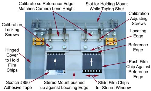
A diagram of the jig is attached.
Calibration
- If using the jig for the first time, it is best to calibrate it to
your camera. Once calibrated, no further adjustment is required (unless
mounting film from another stereo camera). To calibrate the jig, loosen
one pair of locking screws, and turn the associated pair of adjusting screws
until the reference edge is at the correct height for your camera. Then
tighten the locking screws to fix the reference edge in position. Either,
or both reference edges may be adjusted. It may take a few frames before
you finalise the calibration of the jig. Adjustments small as 1/8'th of
a turn can make all the difference, so be patient.
Use
- Place the jig on a light box with the locating cover open. Place the
stereo mount into the jig with: the inside surface of the mount facing
you; the rounded apertures towards the reference edge; and the edge of
the mount tucked under the reference edge lip. The jig may be used in either
orientation, depending on whether the finished stereo mount is required
to have the tape across the top (use as shown in the diagram), or across
the bottom (use up side down to diagram).
- Place the film chips on top of the round cornered apertures - the left
image is placed back-to-front over the right side aperture, and the right
image is placed back-to-front over the left side aperture.
- Fold down the locating perspex cover to partly hold the film chips
in place.
- Push each film chip up against the reference edge to locate each chip
vertically - and also make sure the stereo mount is also pushed up
against it's locating edge.
- Set the stereo window by sliding the chips horizontally until satisfied.
At this stage it is handy to be able to place a pair of stereo viewing
lenses over the jig to see the magnified image as it is in the hand viewer.
(Space does not permit a full discussion of how to set the stereo window.
If necessary, consult a fellow stereo worker, or see Ferwerda's "World
of 3D".)
- If for any reason the baseline alignment is not correct, or within
acceptable limits, re-calibrate the jig.
- Tape the film chips into position with Scotch #850 tape along the film
edge protruding from under the locating cover. To ensure that the film
chips don't move, push down firmly on the hinged cover while placing the
adhesive tape into position.
- Remove the mount, check the image in the stereo viewer, and tape the
mount shut across the top. A special slot at the back of the jig is provided
to hold the mount upright while taping the mount shut.
Notes
1. The jig will reveal any variations or deficiencies in other factors
that affect the vertical alignment (or baseline alignment) of the stereo
image. Such factors are:
- If the stereo mounts used are not accurately made, any variation in
the vertical position of apertures will result in the baseline alignment
appearing incorrect. Use of the precision cardboard stereo mounts will
ensure satisfactory performance in this regard.
- Variation in the film path through the camera could introduce some
variability in baseline alignment.
2. If for any reason you have dismantled the jig and are going to re-assemble
it, or need to reset the calibration of the jig back to the nominal "factory"
settings then note that there are several alignment markings cut into the
baseplate of the unit. These lines are just a few millimetres long, and
can be best seen by examining the baseplate from underneath. The following
alignment markers can be seen, working from top to bottom as oriented in
the diagram:
- One pair towards the top of the jig for aligning the leading edge of
the 10mm thick bar across the top of the jig.
- One pair for aligning the white "locating edge" plastic.
- Two pairs of markers, one for each reference edge. These are 3mm away
from the position of the white locating edge.
- Two other pairs of markers near the edge of the base plate - these
just mark the position of the rebate in the baseplate and were used during
manufacturing.
3. If the mounts being used are too thick, then the depth of the rebate
in the baseplate could be increased to cater for thick mounts. The jig should
cater for thicknesses in the range 0.5mm to 0.8mm.
- Return
to Victorian 3D Society Inc. home page -
Feel free to send any questions or comments to The Society Secretary: maxhem@iprimus.com.au
The information contained in these Web pages may NOT be used or reproduced
for commercial purposes.
