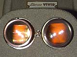
with lamps dimmed

|
| The TDC 116 Projector with lamps dimmed |
Over the last 3 or 4 years there has been a dramatic increase in the number of Club members with projectors, from around 2 or 3 up to around 7 or 8, with many of these projectors being TDC models from the USA.
As most projectors coming from the USA need some form of modification to operate on our mains voltage, and given that it would also be an opportunity to bring such projectors up to date by using better lamps, this article describes in detail the modifications made to a TDC-116 projector to fit low voltage halogen lamps to it.
Taking into account factors discussed in Part 1 of this article, it was decided to modify a TDC-116 projector so that low voltage quartz halogen lamps could be used with it. The modifications described here follow along similar lines to those undertaken by Max Hem on his TDC-716 projector, which has been used extensively at our Club meetings.
The original lamps in the TDC-116 were a CZX-120Volt / 500 Watt. The lamps chosen to replace these are the popular EHJ-24Volt / 250Watt, which require a completely different lamp socket.
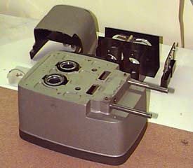 |
| Fig1: The TDC 116 Projector Stripped ready for modification. |
The new lamps require a "2-pin" socket with 6.35mm spacing. This is a standard pin spacing, and no difficulty will be encountered locating such sockets. However it may be difficult to find sockets rated for use with 250W lamps. In this particular modification some lamp sockets were salvaged from old mono projectors.
In designing a method for mounting the new lamp sockets it is important to allow some facility to adjust or fine-tune the position of the lamp. This requires an ability to move the lamp plus or minus a few millimetres from its nominal position. This adjustment should allow the lamp height, sideways position, and fore-aft position to be fine-tuned.
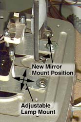 |
| Fig2: Mounting for new lamp sockets and re-positioned mirrors. |
Initially the lamps were placed at the same position as the old lamps. The height was set as shown in Figure 3, which allows room for the filament image from the mirror to be positioned above the lamp.
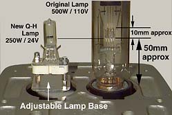 |
| Fig3: The nominal positions of the old and new lamps. |
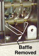 |
| Fig4: Less air was directed at the lamps. |
The issue of cooling air for the new lamps is a little more tricky than
for the old lamps. It is possible to "over-cool" quartz halogen
lamps, where as the original lamps basically needed as much air as they
could get. Also as the amount of heat generated is half that of the original
lamps, less air is needed. Three factors have been altered from the original
design that reduces the amount of air fed around the lamps:
So far these arrangements seem satisfactory.
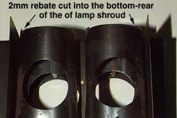 |
| Fig5: A rebate inthe base of the lamp flue allows for the mounting plate for the new lamp base. |
To allow for the new lamp sockets to be fitted, a rebate of approximately
2mm was cut into the base of each flue surrounding the lamps. This is shown
in Figure 5.
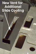 |
| Fig 6: Additional slide cooling vent. |
A new ventilation hole was added in the top deck of the projector, just
in front of, and beneath the slide gate (between the slide and the projection
lens). Figure 6 shows the new arrangement. Note that a hole also had to
be cut in the base of the black slide gate shroud. With this arrangement
the slide gate temperature rises just 15 Celsius degrees above ambient,
which is evidence of excellent slide gate cooling.
It was required to obtain satisfactory light coverage for slides up to 31.5mm wide x 23mm high. To obtain this performance some fine tuning of the alignment of the various components in the projector was required. In summary the following alteration were made:
|
| Fig 7: Lamp alignment can be inspected visually with dimmed lamps. |
The alignment of the lamp can be inspected by holding a simple low-powered positive lens between the projection lense and screen (eg: a pair of glasses). Figure 7 shows the correctly aligned lamp.
A 500W power transformer is required to run the low voltage lamps, and for many this expense (and weight) will make this modification unacceptable. The transformer is external to the projector, and the power is fed to the projector via a cable 2m long, terminated in a 12-pin Cinch-Jones connector that replaces the original power inlet connector. See also the attached circuit diagram.
The primary of this transformer has several taps (260V, 240V and 220V) so that the lamps can be operated at low, medium, and high settings (respectively). Also a 100V and 90V taps were provided so that the original 110V/60Hz fan could be used. (As Australian line frequency in 50Hz, a 20% reduction in voltage will prevent the 60Hz motor from running too hot).
The primary circuit has a lamp dimmer circuit included in it (which can be bypassed with a switch in case the dimmer circuit fails open, and also to remove any residual voltage drop when turned fully on).
The secondary winding is nominally 50 Volts with a centre tap (25-0-25V). The lamps are run in series, and fed with 50 Volts to limit the current in the cable from the external power transformer. The junction of the two lamps is connected to the centre tap to balance out the voltage on each lamp.
Allowing for losses in the connecting cable, the lamp voltage can be varied from 23 to 25 Volts using the various taps in the transformer. Over running the lamp gives more output, but dramatically reduces the lamp life.