
- Improving the Performance ofa Classic Tannoy Driver -

This article describes my experiences with a pair of 15" Tannoy MonitorGold dual concentric speaker drivers. These were purchased at a garage salea few years ago in the cheapest and most basic original Tannoy box thatI have heard of. Now I have them in a much better and bigger box and havemade some other changes. The speakers started out sounding promising. NowI think they sound extremely good. This article should have enough in itthat could be applied to other speakers too.
Among their advantages are that they are efficientenough to allow the use of low power class A amplification, in my case ahome-built single-ended triode amplifier. High efficiency is a great virtuein speakers. Among other things it allows amplifier design to be freed ofthe compromises and/or expense that are required for high power and highgain. Also high efficiency speakers tend to sound rather more "effortless";perhaps due to less heat being dissipated in their voice coils.
Unfortunately there is no free lunch. If you wanthigh efficiency, you must either give up low bass or small, neat boxes;the physics says you can't have both. In my case I have bass down to 20Hz,high efficiency and boxes the size of domestic refrigerators, but don'tthink this means the speakers give only big sound. They can be detailedand delicate too.
The Original Boxes
The original Tannoy box was a Lancaster enclosure(54cm w x 31cm d x 84cm h) with a simple slot cut in the front panel. Afriend bought a pair of 15" Monitor Golds in a nearly identical enclosuretraded in at a local HiFi shop. In this case the port was sealed up, apparentlyat the Tannoy factory. These sound OK but with even less bass than my portedversion. Both Lancaster versions sounded rather congested compared to thedrivers in my new big boxes and with the various improvement described below.
One of the problems I had with the Lancaster box was that it is too short.When I put it on some bricks to get the driver up to seated ear height thesound opened up considerably. Otherwise it sounded a bit "sat on".Not so easy to fix was the problem that the bass sounded rather tubby andnot very deep. The tubby sound was I think due to fairly large thin panelswithout any bracing. The lack of deep bass was a problem due to the boxbeing simply too small, even though by modern domestic standards it wasbig. Some of the congestion might have been due to the very heavy grillcloth.
A Horn Enclosure?
I wrote to Tannoy asking them about horn enclosuresfor these drivers. They kindly sent me three enclosure plans. One of thehorn plans (Professional or Rectangular GRF) didn't appeal because the driverwas placed even lower than the Lancaster and I already knew that it wasnice to get the drivers on axis at ear height. The other two were horn enclosuresintended for corner placement (GRF and Autograph). The Autograph designin particular looked really nice. It has a short front horn and a foldedrear horn. The currently produced Westminster enclosure seems to be a rectangularversion of this box. It has approximately 600 litres total volume. The fronthorn loads the main cone from around 200Hz to 1KHz and the folded rear hornloads below 200Hz. The crossover allows the input of the tweeter (from 1KHz)to be stepped up to match the increased output below 1KHz. The rear hornsplits part way through the box to exit next to the two side walls of thecorner. Thus the corner extends the horn mouth into the room. Horn loadingthe bass cone should be a good thing in theory. It should reduce driverdisplacement for any particular output level and thereby reduce distortion.I expect the Autograph sounds very nice but have not heard it. Unfortunatelyplacement hard into the corners wasn't going to suit my room and the wood-worklooked very complex.
Back to a Simple Box
The horn designs were drawn in the 1950s so wereintended for earlier versions of the 15" dual concentric but had beenmodified (only the driver mounting) for the 3838 and 3808 drivers from around1980. This suggests to me that the parameters for the 15" dual concentricshave changed very little from model to model and published Thiele and Smallparameters for later drivers could give an indication of what to expectfrom the earlier ones. [This seems supported by the measured HPD parameters]A friend with box modelling software plugged in the 3838 parameters to seewhat was suggested for a flat alignment. It came up with an impossibly smallbox, tuned impractically with a -3db point somewhere well above 100Hz. Isuspect the program expects higher Q drivers when it tries to find an optimum.Be carefull that software doesn't tell you nonsense.
I wrote again to Tannoy and asked for suggestionsfor the best simple box for my drivers. They suggested a 300 litre box withfour ports, each of 100mm diameter and 250mm length and this is what I havebuilt. Tannoy claimed that this box should achieve a -3db point at about35Hz with the 15" Monitor Golds. This is a BIG box and I think it isabout 50% larger than any of the commercial reflex boxes produced by Tannoy.300L is about 10 cu.ft. Tannoy did not publish Thiel and Small parametersfor the Monitor Gold for the simple reason that the drivers predate Thieland Small's work. The free air resonance however was published as the sameas the 3838 (20Hz), obviously the drivers are about the same area, and beingused in some of the same boxes could not be grossly different. As a realitycheck my friend modelled the 3838 parameters in the 300 litre box. The responsewas reminiscent of a sealed box alignment with Q of 0.5, a transient perfectbut not perfectly flat response. Specifically, the response was very graduallyand smoothly rolling off from well above 100Hz and was 6db down by 35Hz.Perhaps you could call that the -3db point if you allow the mid-range tobe plus 3db or perhaps the 3838 is not such a close model for the MonitorGold. Whatever the theoretical response should be the recommended box givesstrong, deep, well-balanced bass in practice using corner loading but thebass is a little weak if the speakers are out in the middle of the room.
Minimising Box Colourations
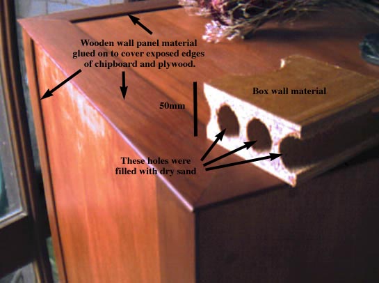
Although a rectangular box is simple compared withhorns there are still some important considerations. A major issue is minimisingbox colouration. I made the panels from some scavenged office partitionmaterial consisting of a chipboard core faced with plywood on both sides.Overall the material is 50mm thick, thicker than most speaker box material.It had 25mm holes running vertically through the core, presumably to reduceweight, which I filled with sand. The holes were plugged with bits of oldmattress foam and then sealed with automotive "bog". In additionto thick panels and sand-damping, I placed two shelves inside the boxesfor bracing. These have cut-out areas to allow air movement but the remainingwood ties opposite panels to each other, braces along the face of each paneland triangulates across the corners. Consider that even slight panel vibrationis distributed over a much larger area than the speaker cone and could contributesignificant sound output. I doubt it would be possible to go to far tryingto kill panel vibrations.
When making these plans I received the interestingcomment that the old Tannoy drivers can produce a very modern sound withsuch construction but that some people have been disappointed if part ofwhat they liked about the older Tannoys was the warmth of box colourations.Personally I doubt that anyone would prefer the tubby sound of the Lancastersover the improved clarity, dynamics and extension of my big boxes.
The dimensions of the box were made as narrow aspossible side to side without boxing in the driver very closely, mainlyfor visual aesthetics. I then tried to avoid making the height or depthof the box simple multiples of this internal width. This was to avoid multipleinternal standing waves that might reinforce each other. The box ended upbeing 57cm (w) x 63cm (d) x 134cm (h) external dimensions. Inside the boxthe bracing shelves are just a little above and below the driver. The intentionwas to put most bracing where the driver might try to move the panels mostbut also avoid any very large unbraced sections. The bracing was also placedso that the sections of panel between the bracing were of different lengthsto spread the frequencies of any residual resonances.
Damping material for the space inside the box seemsto be a bit of a black art. In a vented box its function is to absorb higherfrequency radiation from the rear of the cone that might otherwise bouncearound and excape through the cone or vents. Also it should damp lower frequenciesthat might set up standing waves within the box. I applied a little readingand a little thought to this area. I am happy enough with the initial resultsthat I havn't tried any experiments in this area. Ideas I used were 1) Woolis supposedly a better damping material than polyester, glass fibre etc.2) Air particle motion is always at a minimum at the box wall, thereforedamping material placed on the wall has least effect. 3) A clear thoughnot straight path must be available between the driver and the vents andthe vents should be well clear of damping material and the box walls.
I was able to buy batts of pure wool intended forceiling insulation. Two of these went in the box supported by the shelfabove the driver and so the top quarter of the box is full of loose wool.This should make it hard to sustain standing waves along the long (top tobottom) axis of the box. Another batt was stapled to hang loosely aroundthree sides of the middle section of the box behind the driver. A fourthbatt is in a U shape in the bottom section of the box. The four ports areon the front baffle in the lower section of the box. Immediately behindthe port opening is a large acoustic foam tile, the sort with wedge patternson the surface. Measurements of the port output indicated virtually no higherfrequencies escaping the port. More subjectively, when I had my head andshoulders through the driver hole, hammering the staples holding the woolin place the metal on metal sounded like dull thuds.
Moving the drivers into these well damped and bracedlarger boxes gave extra octaves of bass and a big improvement in the tightnessand clarity of the bass and mid-range.
Moving the Beasts
With thick, sand filled walls the boxes ended uprather heavy! Two adult males struggle to carry one of these speakers. Tomove them within the room I wanted some carpet sliders but none of the devicessold for this purpose looked like they would take the weight. Then I noticedthe smooth, hard, rounded plastic buttons that are glued to the surfaceof roads to mark lanes. Four of these glued to the bottom corners of easchbox makes them fairly easy to push about over carpet.
Speaker Placement
As mentioned already just putting the Lancasterboxes on blocks so the driver was at ear height was a worthwhile improvementfor bigger, more open sound. In the big boxes the driver center is at myseated ear height. This does introduce a potential problem.
Roy Allison has pointed out that a dip in the response of a speaker placedat ear height can occur a bit over 100Hz as this is the distance to thefloor and back for half a wave length. Thus the reflection from the floorcomes back out of phase, unloads the driver and causes a 3db dip in efficiency.Not thinking of any of this I had inadvertently placed the speakers in theroom such that the distance from the driver to the wall behind was aboutthe same as the distance to the floor. This would result in a predicted6db upper bass dip. This led to a subjective effect that was initially surprisingfor me till I worked out what I think was going on. With a bass instrumentonly playing up and down through its range the sound was fine and no responsedip was apparent. If some mid-range instruments joined in the bass wouldkeep appearing and dissapearing with no obvious pattern. I think I learnedsomething about masking and the audibility of dips. 
So how could I avoid the dip with the height ofthe driver fixed? I used BestPlace software (Mac version) which was freefrom RDL Acoustics. It models just the loading/unloading effect of the threenearest surfaces; it is not a whole room acoustics model. By trial and errorI found a position for the boxes toward corners that was predicted to givea gradually rising bass response without any serious dips, roughly equaland opposite to the gradually rolling off response predicted above (IE about+6db of boost at 35Hz). The position has the side wall of the corner closerto the driver than the distance to the floor and the distance to the wallbehind is further away. Ultimately a corner gives +9db at the lowest frequency.Combining the modelled frequency response with the predicted boost gavean expected resultant -3db point around 30hz. The measured result was betterthan expected, flat to 20hz. I guess the wavelengths are long enough at20Hz to get additional boosting from further surfaces, or perhaps the speakersare just better than expected.
Subjective impressions are consistent with allthis modelling; out of the corners the bass sounds a bit thin. In the rightposition towards the corners the speakers sound well balanced with verydeep but not boomy bass. Bass instruments can be followed even with plentyof other instruments playing but are not obtrusive. The speakers are alongthe shorter wall of my lounge room so facing the speakers directly towardsthe couch enables the drivers to be sufficiently close to the side walls.The corner placement is also fortuitously a good way to not take up to muchfloor-space. I point all this out because I started out with the receivedwisdom that speakers need to be away from walls to "breath". Makesure you don't put speakers equidistant to the surfaces of a corner. Thatwill cause a 9db hole followed by a 9db boost lower down.
Getting Rid of Dry Contacts
These speakers have quite a few non-soldered contactsthat might have corroded with time. Minimising the number of dry contactsgave a subjective improvement in both treble quality and quantity, mostlythe former. The crossover has two switches, in series with the tweeter.One switch ("energy") selects taps on a choke to step the tweetersignal up or down. The middle position was initially selected for the besttonal balance and hardwired. The other switch ("rolloff") givesa flat position of various amounts of rolloff. I hardwired the flat position.
Another set of dry contacts is a plug and socket arrangement on the chassisof the driver. The socket can be reversed to act as a convenient set ofsoldering lugs, like a little tag strip, to solder the speaker connections.
Opening up the Crossover Box
The crossover was sealed up in a plastic box. Iopened it by drilling out the four rivets in the corners. Two screws holda board in the larger part of the box. These were undone to allow the electricalequivalents of the switch positions described to be hardwired directly onthe board. Initially I retained the original wire except the lead to theswitch box. Later I replaced the wire with van den Hul wire and can't claimto have heard any improvement. Hardwiring seemed to make far more difference.When I rewired I moved a few wires around so that I could later biamp orbiwire if I so chose. That is not too hard to work out.
I replaced all the crossover caps with equivalentvalue MIT or Solen polypropylenes. This was not too expensive because thelargest value required is 16µF. The 16µF was made by parallelinga couple of smaller values. This also was a subjective improvement in treblequality and quantity. The larger caps don't allow the lid of the crossoverbox to be put back on. I put some caps on the inside and hung others offthe underside of the board, then screwed the board back into the plasticbox without the lid. This seems quite robust. The whole thing now livesloose in the bottom of the speaker box on a short set of wire soldered toa removable binding post plate on the back of the box. Note that the plasticcrossover box is important; it helps to hold the chokes together. Otherwisethey would rely on just a bit of tape.
Surgery on the Dustcap
Removing the dustcap in front of the tweeter givesa worthwhile improvement in treble quality, and a little more quantity.I think the earliest and latest versions of the dual concentric do not havethe dust cap and the 1980ish 3838 has a more transparent looking dustcap.The idea was suggested to me by a guy I met in a TV repair shop in a littletown in Tasmania who was quite a Leak and Tannoy enthusiast. He insistedthat the glue holding on the dust cap was readily soluble in acetone. Itis soluble but not quite so easily as I was led to believe. The method Iwas told was to paint acetone liberally along the glued edge of the dustcapto soak the paper and glue, then slide a knife between the dustcap edgeand the cone to neatly lift the cap off with no damage to the cone or cap,and therefore reversible. I tried this. It seemed to be working OK but thenI lost a little bit of cone paper when I hit a patch of less well dissolvedglue. In my experience the glue softened but didn't really let go completely.Work very carefully at this! Acetone is very volatile so you have to keeppainting it on as you work. When it was done the improvement was considerable.More open and airy top end. Also just plain more top end, perhaps a littletoo hot.
Getting the Balance Back
Various changes had improved treble quality butalso seemed to give just a little more quantity too. Eventually the cumulativeeffect was just a little too much top end. At that point measurements showedthe tweeter output to be broadly about 2db above the woofer output. To fixthis I went back to the crossover and moved the hardwired crossover to thesecond lowest tap on the "energy" choke. The choke does two things.Firstly it is part of a conventional LC filter. Also it acts as an autotransformerwith 5 taps. The second lowest is the driven tap connected to the inputvia a capacitor. The nominally flat position that was originally preferedis the middle tap. Moving down to the second lowest tap retored the correctsounding balance and as a bonus the treble clarity seemed better still.Perhaps this was from using the direct position on the choke, neither steppingup or down.
Tidying Up
I worried that dust, insects, bits of metal filingsetc. might find their way into the magnet gap having removed the dustcap.I put some double-sided sticky tape along the foam on the front edge ofthe driver chassis and stretched some fine black speaker grill cloth overand trimmed the edge. The cloth was further secured, and the ragged edgehidden, by an open black-painted metal grid that is clamped to the frontof the chassis with the 8 bolts that retain the driver in the box. The metalprevents excited kids from crashing into the driver. The cloth keeps outdust etc and is more acoustically transparent than the original dust cap.I think it probably helps being at the horn mouth rather than closer tothe horn throat. I noticed no loss of sound quality with the addition ofthe cloth and it looks nicer too.
For while the boxes stayed rough looking but eventually I got around tosanding back the plywood and glueing on some thin decorative strips of woodover the exposed chipboard edges. The whole thing was given a coat of astain/varnish and I think they now look quite presentable in a solid, slightlyold-fashioned kind of way, which is only appropriate.
These speakers really rewarded this tweaking. Non-audio types are oftenamazed that I can get the best sound they have heard from gear that is mostlyhome-built valve electronics or 1960s vintage. A friend has Monitor Goldsstill in Lancaster boxes and the sound is not nearly as good.
PS: What is Going on in that Cross-over?
A few people have suggested to me that the Tannoycrossover is unduely complex and suggested simplifying it. I think the crossoveris actually just about right. Everything is there for a good reason. Thevarious level and roll-off controls provided on different Tannoy modelsdon't require any extra components other than the switches themselves; theyjust take advantage of parts that have to be there anyway. So, how do theywork? Firstly there is an LC low pass filter for the bass section and acorresponding CL filter for the high pass section. So far very conventional.Altering that would require some carefull thought about the offset of thetweeter to the rear and the phase-shifts associated with the filter. Fivetappings on the winding of the high pass inductor enables it to double asa single winding transformer (autotransformer). The "energy" switchselects the different taps allowing the signal to be stepped up or downa few db. A feature for the price of a switch!
From here it gets a bit trickier. The rest of the crossover is there toequalise the response of the tweeter which otherwise would be far from flat.Some horns tweeters have a flat on axis response but that (like most speakerdrivers) is at the expense of more and more narrow dispersion with increasingfrequency. Instead the tweeter in the Tannoy is a constant dispersion horn.In order to get constant dispersion a falling response with increasing frequencyis unavoidable. At the low end the efficiency is extremely high and stillnot bad in the top octave. Thirty ohms in series with the tweeter give alot of attenuation for the low end and the high end is recovered with acapacitor that progressively bypasses the resistance at higher frequencies.If the cap were disconnected one would get a treble roll-off. If the 30ohms were partly bypassed one would get a lesser roll-off and if the capwere connected in parallel with the tweeter the 30 ohms and cap would formand RC filter to give an even steeper roll-off. Thus an extra switch makesa feature out of necessity and provides a selection of treble roll-off choices.
Finally, in parallel with the tweeter is a resistor,a capacitor and an inductor in series. These, I'm told, are there to pulldown a response peak at about 2 Kohms. In the Monitor Gold crossover theseare fixed but later versions of the crossover have turned these into a controlfeature also providing a switch that varies the value of the resistance.Thus the later crossover gives the possibility to reduce the effect to givea mid-range peak, or increase it to give a mid-range dip.
I can only think of one way to get rid of someof the crossover bits (other than the switches) without causing more troublethat it is worth. That would be to bi-amp the speakers and build the tweeterequalisation into the amplifier. That might have some nice consequences.The tweeter is so efficient without the equalisation that one could choosea class A amplifier design with virtually no contraints. One could pickthe most linear triode capable of putting out a couple of watts and haveplenty of power.
Comparison with 3838 Sound
How do the older Monitor Gold drivers sound nextto the more modern 3838 drivers? A friend brought some 3838s to my placein reflex boxes about 2/3 the size of mine. The first obvious differencewas lower efficiency. Equal volume required an extra 2 clicks on my steppedvolume controls which amounts to about 4db difference. Overall the Goldssounded more "effortless". "Effortless" is a commondescription of the sound of efficient speakers but another factor couldhave been my low power amp being 4db closer to clipping with the 3838s.There was a small region of the mid-range that seemed a little smootheron the 3838s, perhaps the effect of the struts on the rear on the cone preventingsome cone breakup that the Monitor Golds might have. The older driver wasprefered at the frequency extremes, deeper bass and more "airy"top end. Otherwise the family resemblance was clear and the sound was quitesimilar.

Acknowledgement
I would like to thank PeterCampbell for his kind permission to reproduce this paper at this website.