 |
The Leak Varislope Pre-Amplifer Series |
 |
The Leak Varislope Pre-Amplifer Series |

In 1952 Leak introduced the "Vari-Slope" pre-amplifier, replacing
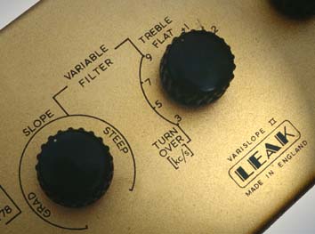
the RC/PA/U preamplifier. The Varislope featured a low-pass filter circuit
with variable turnover frequencies and variable cut-off slopes from approximatley
5dB to 50dB per ocatve. The circuit was novel as it was implemented solely
with resistors and capacitors within a negative feedback circuit. The Leak
literature states:
The new "Vari-Slope" pre-amplifier has a refinement which will doubtless set the pattern for future high-fidelity reproducing amplifiers. This advance consists of a variable-slope "electronic" low-pass filter operating on negative voltage feedback principles. No inductors ("chokes" are used and all their disadvantages are completely eliminated.
Shown below is the basic circuit of the Varislope filter. This circuit is taken from the circuit of the "Varislope Stereo" preamplifier which was issued later in 1958, however the basic operating principle remain unchanged in the various Varislope circuits.
The twin-t circuit was discussed in the April 1945 issues of the Journal of the Acoustical Society of America, Vol 16, No4, pp 275-279. A similar circuit with fixed-slope was also used by Williamson in the pre-amplifier designed for operation with the famous Williamson power amplifier (Wireless World April 1947).

The circuit uses a twin-T resistor-capacitor network in the forward path
of the pre-amplifiers gain stage. The twin-T circuit on its own is a nulling
circuit, giving nominally zero output the null frequency. For instance the
null frequency chosen for a pre-amplifier might be 16kHz - the slope of
the attenuation curve above and below the null frequency is not very high,
howevre the Q of the overall circuit may be increased by including the circuit
within a feeback loop.

To provide a variable slope characterisic, a variable resistor is placed in parallel with the twin-t circuit. When this resistor is open circuit the filter has the highest Q. To provide different turn-over frequencies a variable capacitive load is placed on the output, and for the lowest turnover frequency an additional cpacitance C1 is switch into circuit (unlike the Williamson circuit in which the actual capacitors in the twin-t were switched in value). In later circuits the resistors R1 and R2 were replaced with the famous Baxandall tone control circuit (developed by Peter Baxandall), thus giving the ability to have treble boost simultaneously with high-frequncy filtering.
At the time, such a circuit was considered to be
useful in filtering out distortion from the gramophone records of the day,
or in filtering whistles and high frequency chatter received on AM broadcasts.