 |
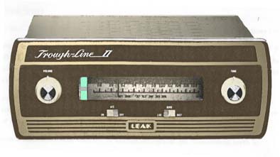
Leak Trough Line II FM Tuner |
 |
Leak Trough Line II FM Tuner |

At the time this Tuner was released it was an advanced design for a consumer FM tuner. It's main design feature was a very stable oscillator circuit, preventing significant drift of the tuner (many tuners of the time needed to be periodically re-tuned as they warmed up). The oscillator in the Trough-Line does not use conventional wound coils or inductors, but instead a tapped transmission line. A good description appeared in "HiFi News":
Leak have adapted for their oscillator, a variation on the quarter-wavelength line type of resonator. It has been found in communications engineering that for frequencies in the 100Mc/s region and above, it becomes increasingly difficult, for a multitude of reasons, to make the conventional coil and condenser combination operate satisfactorily; the chief among these reasons are the capacitance inherent in the coil, and the inducatnce in the condenser. Now, a quarter-wavelength section of transmission line, shorted at one end, behaves as a parallel resonant circuit of very high Q and electrically stability, while the mechanical construction of such a device leads almost automatically to great rigidity (and hence stability). The Q being high, tapping down will still permit adequate voltage at the output; and as the coil is a straight peice of wire, selection of optimum tapping points is obviously much facilitated. Below is a diagram of the resonantor in the Leak circuit, and also the bread and butter version. It is clear that the Leak resonator is not a true quarter-wavelength section, its length being under 6 inches, but its frequency in the Trough-Line is controlled by added (variable) capacitance.

The oscillator circuit has a quoted drift of 15kHz with out AFC. With the AFC circuit switched on, this is further reduced to 3kHz drift (or approx 0.003%).
The Tuner was originally issued as a mono unit, with provision for adding a stereo de-multiplexer later. Subsequent models were also available with solid-state stereo decoders. These decoders could have been designed better, and it is worth replacing the original decoder with a better circuit. (It seems likely that the original stereo decoder may have had cost and physical size as the main design considerations rather than performance.)
This Tuner has enjoyed a resurgence in interest in the last few years, with advanced external stereo decoders becoming available.
"Trough-Line II" Summary Specification
Circuit Diagram
88-108 Mhz
3kHz maximum drift with AFC on
2 microvolt sensitivity for full limiting
300 Ohms or 75 Ohms aerial input
Cathode follower audio output
Multiplex output for add-on stereo decoder
Valves: 2x ECF80/6BL8, ECC84/6CW7, ECC85/6AQ8, EF80/6BX6, EM84/6FG6 indicator,
EZ80 rectifier.
Weight: 11 lbs